
Nullam dignissim, ante scelerisque the is euismod fermentum odio sem semper the is erat, a feugiat leo urna eget eros. Duis Aenean a imperdiet risus.
Nullam dignissim, ante scelerisque the is euismod fermentum odio sem semper the is erat, a feugiat leo urna eget eros. Duis Aenean a imperdiet risus.
 author
A diamond-coated milling bit is reliable only when substrate preparation, cutting geometry, CVD coating, and final inspection are controlled as one process. TSHZ develops diamond and superhard cutting tools for precision applications. For a buyer, the practical test is whether the supplier can show how each step is matched to the work material, cutting path, and acceptance criteria.
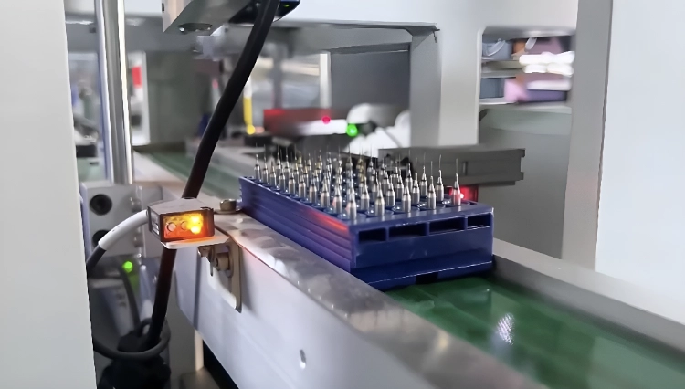
Coating cannot correct an unsuitable substrate or an unstable edge. Production therefore starts with the tool body and geometry required by the finished application, then carries those requirements through surface preparation, coating, and inspection.
For a diamond-coated milling bit, the substrate provides stiffness, shape, and the connection to the machine. Surface condition matters because contamination, burrs, or an uneven area can reduce coating adhesion. The supplier should identify the carbide or ceramic substrate used, the preparation method, and the critical surfaces that must remain clean before coating.
Flute form, edge shape, diameter, and working profile determine how the tool meets the material. For PCB work, small features and brittle laminates make edge condition especially important. Geometry should be measured before coating so the surface layer is applied to a controlled cutting form and any dimensional change can be reviewed.
The surface must be prepared so the coating process can interact with the intended area. The exact treatment depends on the tool and process, but the buyer should expect controlled cleaning, masking, activation, and handling between preparation and coating. Small contamination can become a large adhesion problem later.
The coating stage adds a working surface to a prepared cutting body. Its value depends on process control, coating uniformity, and keeping the coating from changing the intended geometry.
CVD Diamond-Coated Cutting Tools is a relevant product direction for buyers comparing CVD diamond-coated tools. The coating has to reach the intended cutting surfaces while protected areas remain usable for clamping or assembly. Ask how the working zone, edge condition, and masking requirements are defined for the specific tool.
For a diamond-coated milling bit, the surface layer changes the interface between tool and workpiece. Excess material can alter clearance or edge sharpness, while an incomplete layer can leave a wear-sensitive area exposed. TSHZ product materials list reference ranges of 9,000-10,000 HV for Vickers hardness, approximately 0.05-0.1 for friction coefficient, and 1-30 um for controllable CVD coating thickness. These are reference ranges, not universal guarantees; the selected tool and batch inspection report should confirm the applicable value.
Diamond coating is not a universal improvement for every workpiece. It is most relevant when abrasion, edge wear, or chip movement is the limiting problem, such as with graphite, PCB laminates, ceramics, or hard composite materials. Buyers should state the material, abrasiveness, board structure, expected finish, and machine setup so the coating route can be judged against the real cut. For ferrous materials or other chemically unsuitable workpieces, ask the supplier to confirm the coating direction before ordering.
Product families should be compared by feature size, material behavior, tool path, and the consequences of a poor edge. A drilling tool, routing cutter, and specialized CVD tool should not be evaluated by the coating name alone.
PCB Diamond Drill Bit fits hole-making work where hole quality and board-stack behavior matter. Check the required hole size, entry and exit condition, board construction, machine runout, and how the tool will be changed. For a pilot lot, agree on the hole-diameter tolerance and the inspection method before evaluating the complete drilling setup.
PCB Diamond-Coated Milling Cutters is relevant when routing, edge formation, or slot work requires a controlled milling profile. Review the cutter form, machine interface, path, chip evacuation, and the material removed per pass. A milling tool is selected by the cut it must make, not only by the coating name.

CVD tools can be considered where the work material and repeated cutting demand justify a CVD direction. Compare expected wear location, edge form, machine conditions, and inspection plan. The coating route for a diamond-coated milling bit should be connected to a real failure or wear risk, while the selected CVD direction should be checked against the product page and the supplier’s inspection record.
Inspection should confirm that the tool received is the tool that was specified, with usable geometry, a controlled coating condition, and a surface state consistent with the application.
Inspect diameter, length, edge form, runout-related features, and the areas needed for clamping. The exact acceptance points depend on the drawing and tool type. A buyer should approve a measurable list that states the feature, tolerance, inspection method, and rejection point instead of relying on a general statement that the tool was inspected.
Look for uncovered working areas, flaking, scratches, contamination, and damage caused by handling. Inspect the cutting edge at the level needed for the application. Packaging should keep finished tools from striking one another before they reach the machine, and any visible damage should be recorded before the first run.
Record the tool identity, drawing or specification revision, substrate or blank information, batch number, inspection date, measured values, and any accepted deviation. This makes a repeat order easier to compare and helps the production team investigate a problem without starting from a vague product name.
Before approving a pilot lot, ask the supplier to provide one acceptance sheet covering tool identity and drawing revision, substrate or blank information, critical dimensions, coating working area and thickness range, edge and runout-related checks, visible damage and packaging protection, and the disposition rule for a nonconforming tool. This turns “inspected” into an acceptance decision that can be repeated on the next order.
Production control is easier to understand when each step is tied to a possible failure. Poor substrate preparation can affect coating adhesion; an inconsistent edge can change the cut; unsuitable masking can leave a clamping area difficult to use; and incomplete inspection can allow a visual defect to reach the machine. The buyer should ask which record proves that each control was completed.
The finished tool should be reviewed in the same context in which it will work. Check the cutting profile, usable clamping area, edge condition, tool identity, and packaging protection. For PCB work, the board stack and routing or drilling operation matter; for a specialized CVD tool, the work material and wear location matter. A manufacturing process is sound only when its controls remain connected to the intended cut.
Inspection records are most useful when they state what was checked and what happens if the result is outside the agreed condition. Ask how a nonconforming tool is isolated, reworked, rejected, or replaced, and how the replacement is identified. This keeps the discussion focused on repeatable control instead of broad claims about diamond-coated milling bit performance.
For a related decision framework, read Diamond Coated Drill Bits vs Carbide Drills Which Is Better for CNC Machining before finalizing the specification.
A diamond-coated milling bit is produced through a controlled chain: substrate selection and preparation, geometry formation, surface preparation, CVD coating, and inspection. Buyers should connect every step to the work material and cutting path, then approve measurable geometry, coating, and nonconformance checks before shipment. If the supplier cannot provide those controls, request a pilot lot before committing to repeat volume.
Use the contact to share the application, quantity, dimensions, material, machine interface, target finish, and inspection questions before the next review.
Typical checks include geometry, critical dimensions, coating coverage, edge condition, visible damage, tool identity, batch information, and the approved specification. The exact acceptance list should follow the tool drawing and application.
No. Coating is applied to a prepared tool and should not be used to hide an unsuitable substrate or unstable geometry. If accuracy is out of tolerance, check geometry, runout, workholding, and the inspection method before changing the coating direction.
Share the work material, feature, tool path, machine interface, roughing or finishing stage, target finish, expected wear concern, quantity, drawing revision, and inspection needs. For a coated tool, also ask for the applicable coating thickness range and the batch record that supports it.
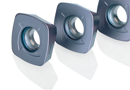
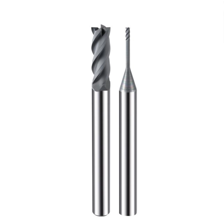
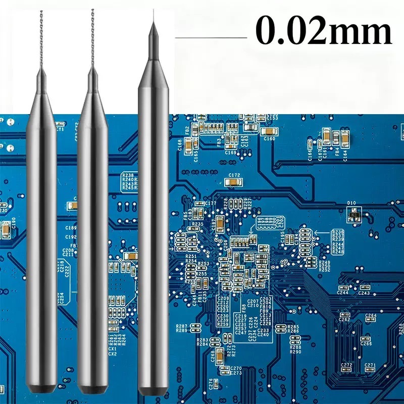
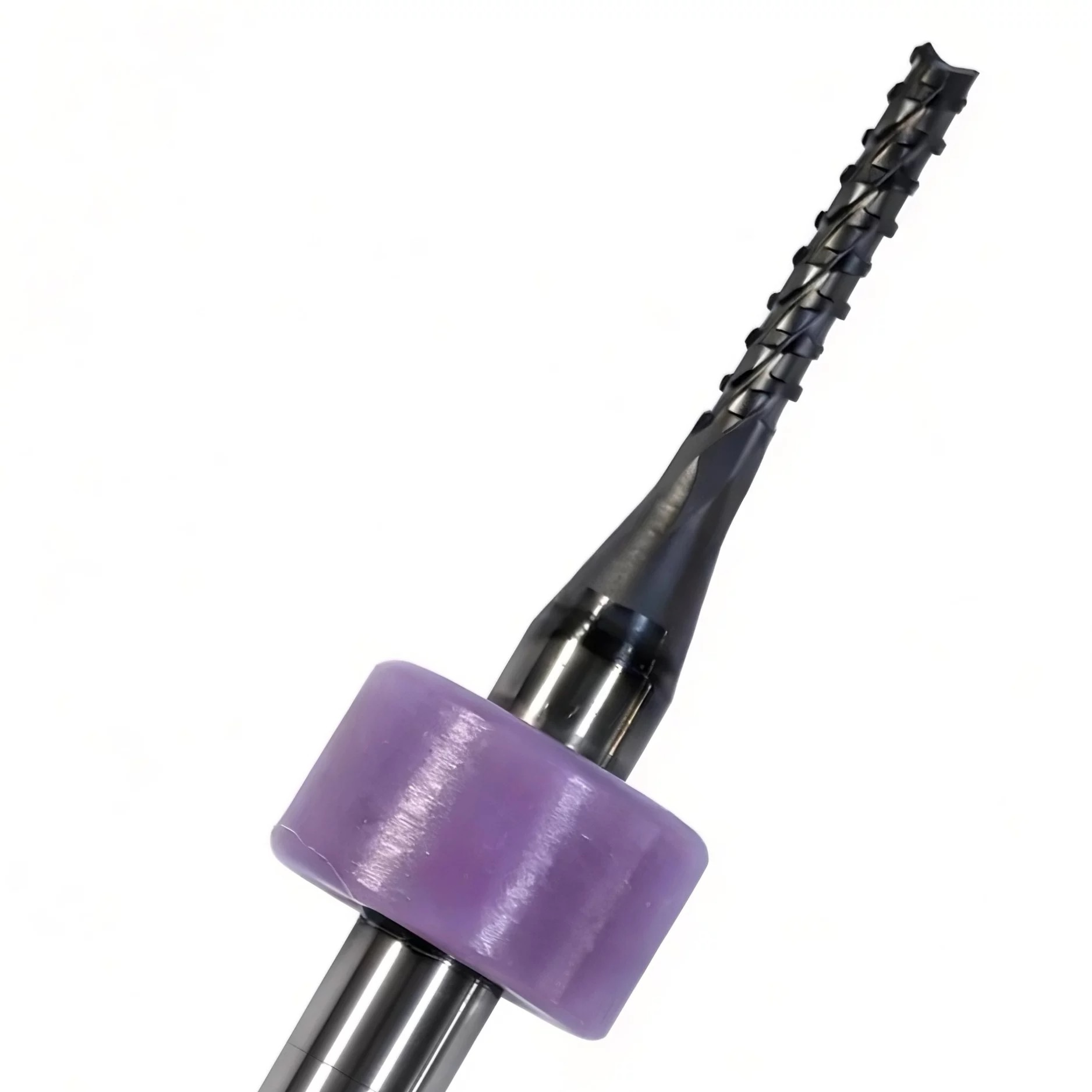
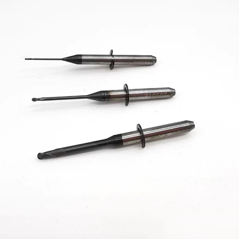
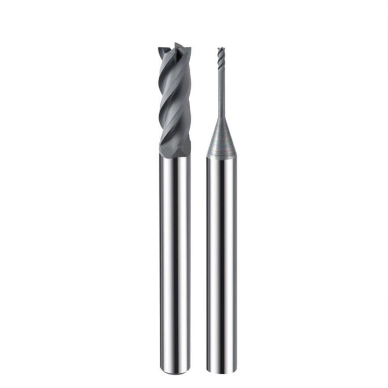
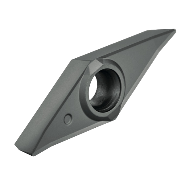
Graphite, Ceramics, and Carbon Fiber are the future, but they are “tool killers.” If you’re still using traditional coating, you’re fighting a losing battle.
Our CVD (Chemical Vapor Deposition) Diamond Coating creates a real crystalline diamond layer on the carbide substrate. This isn’t just a “finish”—it’s a shield.
Why top distributors choose our CVD series:
1.Ultra-Low Friction: Prevents chip welding and heat buildup.
2.Extreme Abrasion Resistance: Maintains sharp cutting edges $20 \times$ longer.
3.Surface Finish: Mirror-like results on the workpiece, zero secondary polishing needed.