
Nullam dignissim, ante scelerisque the is euismod fermentum odio sem semper the is erat, a feugiat leo urna eget eros. Duis Aenean a imperdiet risus.
Nullam dignissim, ante scelerisque the is euismod fermentum odio sem semper the is erat, a feugiat leo urna eget eros. Duis Aenean a imperdiet risus.
 author
Diamond cutting tools can support difficult machining decisions, but machining accuracy is created by the complete cutting system. Tool geometry controls contact and chip movement; a diamond coating changes the working surface and wear behavior. TSHZ develops diamond and superhard tools, while the buyer still needs to match the form, work material, machine, cutting conditions, and inspection method to the actual part.
For diamond cutting tools, geometry determines where the edge meets the workpiece and how force travels through the tool. Small differences can become visible on a surface or feature when the cut is repeated, especially after wear changes the effective edge.
A flat, ball, or rounded nose does not touch the workpiece in the same way. The contact area changes with the path and the surface being created. Choose the tip form from the feature, corner, radius, and finishing requirement rather than assuming one end mill can cover every geometry.
Even a suitable profile can cut unevenly if the tool, holder, spindle, or setup introduces runout. Review the machine interface, clamping cleanliness, tool stick-out, and alignment. Accuracy is not created by the cutter alone; the cutter has to reach the part in a stable position.
The edge has to be sharp and controlled for the intended material. A rough, damaged, or overbuilt edge can increase force, deflection, heat, or burr formation. Specify the edge condition that matters to the job and inspect it at the level required for the feature.
A diamond coating can change wear behavior and the tool-workpiece interface, but its benefit depends on the substrate, geometry, and material being cut. TSHZ product materials list reference ranges of 9,000-10,000 HV for Vickers hardness, approximately 0.05-0.1 for friction coefficient, and 1-30 um for controllable CVD coating thickness; the applicable value must be confirmed for the selected tool and batch.
A coating may help a suitable edge resist the wear mode expected in an abrasive application. That does not mean the tool remains unchanged. Track where the edge wears, whether the finish changes, and whether the tool is approaching a point where geometry no longer supports the part. Record the wear location so a later order can change the right variable.
A coating name does not provide a complete cutting recipe. Feed, speed, depth, coolant or air practice, tool path, workholding, and the work material still need to be defined. Change one relevant condition at a time when a process is being tuned so the effect can be understood, and confirm any cutting data with the supplier for the selected tool and material.
A coated tool can lose practical value if its edge is struck before it reaches the spindle. Store, package, and handle it so the cutting area does not contact hard surfaces. Record visible damage before use; otherwise a setup problem may be mistaken for a coating or geometry problem.
For diamond cutting tools, the correct form follows the surface and path. A buyer should compare the feature first, then the tool family and the inspection point that will prove the feature was made correctly.
Flat Bottom Cylindrical End Mill is a practical direction for planar surfaces, square shoulders, and features where a flat cutting zone is required. Check the corner condition, clearance, work material, machine interface, and how the tool will enter and leave the cut. The flat form is useful only when the part actually needs that contact.
Ball Nose End Mill suits curved surfaces and 3D paths where a rounded end changes the contact as the tool moves. Buyers should check the programmed path, cusp or step-over logic, machine stability, and the finish expected from the operation. The ball form needs a process that respects its changing contact point.
Round Nose End Mill can be considered where a rounded transition or blended edge is part of the component. Review the required radius, clearance, wall condition, and finishing allowance. A rounded profile can reduce a sharp transition, but it cannot correct an incorrect tool path or an unstable setup.

Accuracy needs a shared definition when buyers compare diamond cutting tools. Put the feature, process, inspection, and replacement logic into the order discussion, including the tolerance that will determine whether the first run passes.
Describe the surface, corner, hole, slot, radius, or edge that the tool must create. Add the inspection method, acceptance tolerance, tool condition at inspection, and the point at which a tool is rejected. Where a diamond coating is used, ask the supplier to confirm the applicable coating thickness range and the dimensional change allowed after coating.
Give the machine interface, spindle arrangement, workholding method, accessible space, and whether the process is roughing, semi-finishing, or finishing. Tool geometry is judged in a system; missing setup information makes a precise match difficult.
Use a representative part or material, record the starting condition, and inspect the result before releasing a larger order. If a change is needed, identify whether it concerns geometry, coating, machine setting, workholding, or path. This keeps the correction specific and creates a useful record for repeat orders.
If dimensions gradually shrink across a batch, first check the wear location, measured tool diameter, and the planned change point before changing the tool form.
If cutting load differs between flutes, first check runout, clamping cleanliness, and holder or spindle condition before changing the coating.
If a curved surface shows periodic tool marks, review the Ball Nose End Mill path, step-over, and machine stability before attributing the result to coating wear.
If a thin wall or narrow slot chips, confirm the Round Nose End Mill radius, cutting direction, allowance, and feed before changing the product label.
Accuracy problems should be traced through the complete cutting path. Check the programmed geometry, tool runout, clamping, machine condition, workholding, cutting direction, and inspection method before blaming the coating alone. A sharp tool with the wrong profile can leave an incorrect form; a correct profile on an unstable setup can still produce variation.
When diamond cutting tools are used, the operator or programmer should know where the tool first contacts the part and where the contact changes. This is especially important for flat, ball, and round nose forms. The point of contact affects local load, chip movement, surface marks, and the amount of material left for a later pass. A tool choice becomes more defensible when the intended contact is written into the process plan.
When a diamond cutting tool is being considered, compare the work material, required form, machine interface, wear location, and inspection route as one package. Record what result would trigger a tool change. This gives the buyer a practical way to improve accuracy without promising that a coating can correct poor programming, vibration, or an unsuitable holder.
A useful trial plan changes one meaningful variable at a time. Keep the workholding and inspection approach stable while comparing a tool form or coating direction, then record where variation appears. The result may point to geometry, setup, programming, or wear rather than to one product label. This disciplined comparison gives the machining team a better basis for repeat orders and process changes.
For a related decision framework, read 7 Essential Precision Cutting Tools Every High Accuracy CNC Shop Needs before finalizing the specification.
Machining accuracy is the result of a matched system, not a coating label alone. Choose a flat, ball, or round nose form from the feature and tool path; then confirm runout, workholding, cutting conditions, coating thickness, and the inspection method. Before a repeat order, run a representative trial and record the condition that triggers a tool change. This gives the buyer a defensible geometry-and-coating decision without assuming that a diamond coating can correct vibration, poor programming, or an unsuitable holder.
Use the contact to share the application, quantity, dimensions, material, machine interface, target finish, and inspection questions before the next review.
No. Accuracy also depends on geometry, runout, tool holding, workholding, machine condition, path, and inspection. Coating should be matched to a real wear or surface requirement rather than treated as a guarantee.
Choose by the surface and feature: flat forms suit planar or square-shoulder work, while ball forms suit curved or 3D surfaces. Confirm the path, step-over, and finish requirement before ordering.
Provide the work material, feature, machine interface, tool path, roughing or finishing stage, target finish, expected wear issue, drawing or tolerance, and inspection method. For a coated tool, also ask for the applicable coating thickness range and the batch record that supports it.
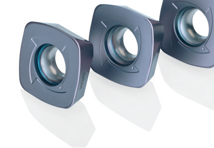
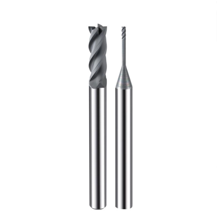
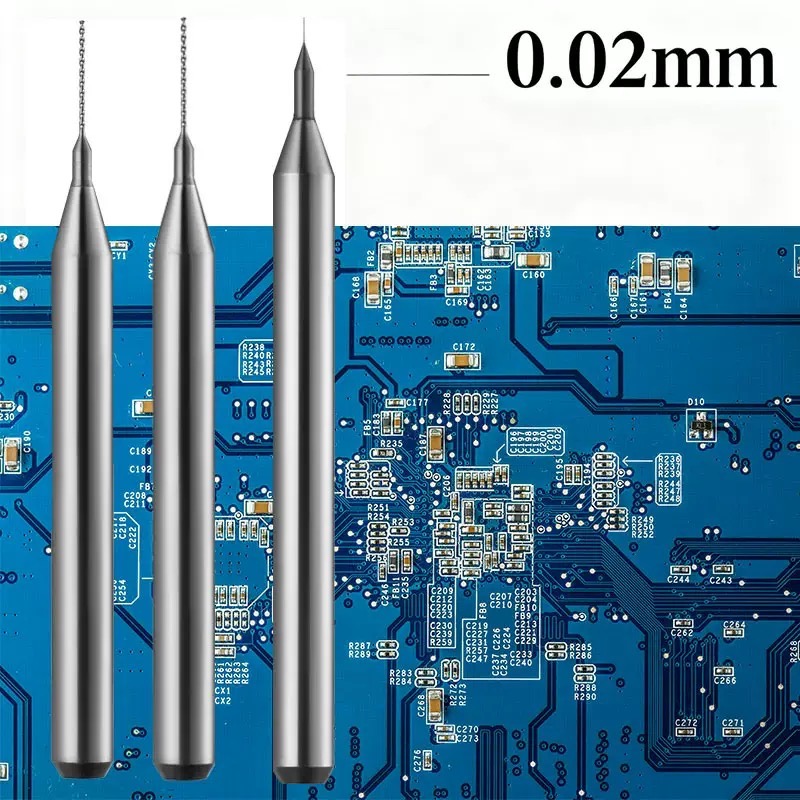
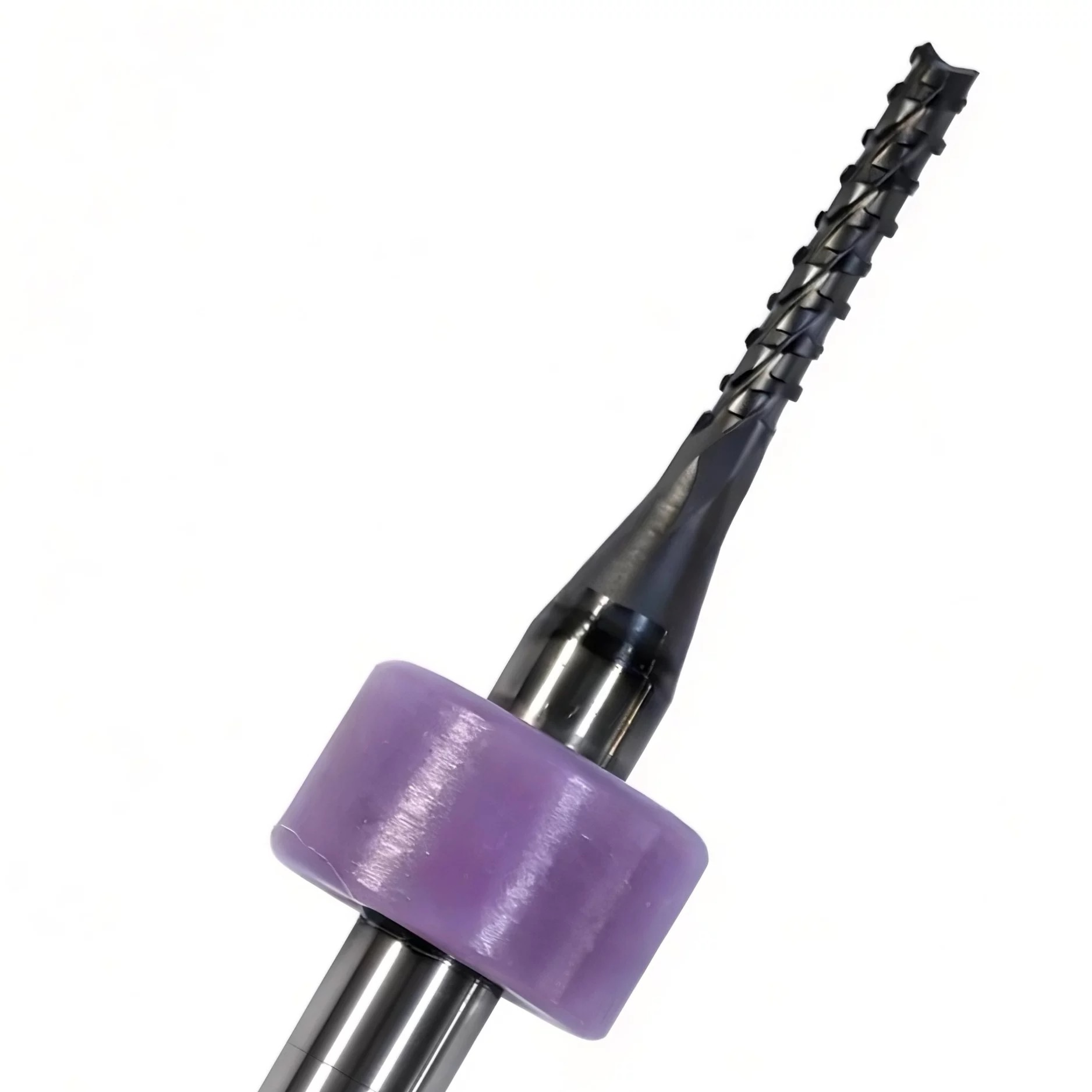
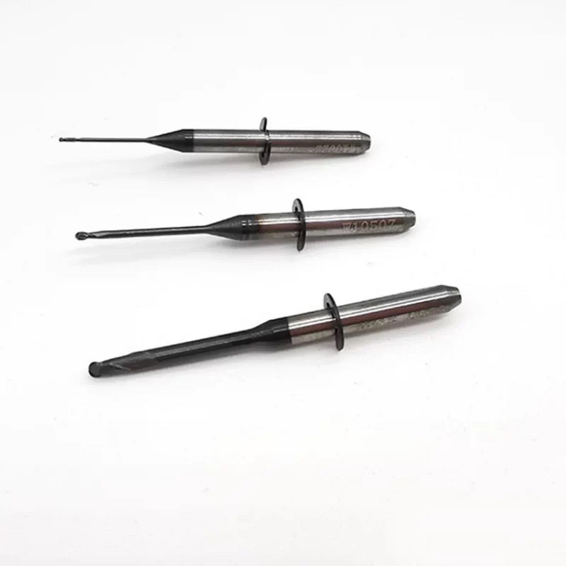
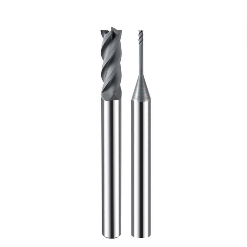
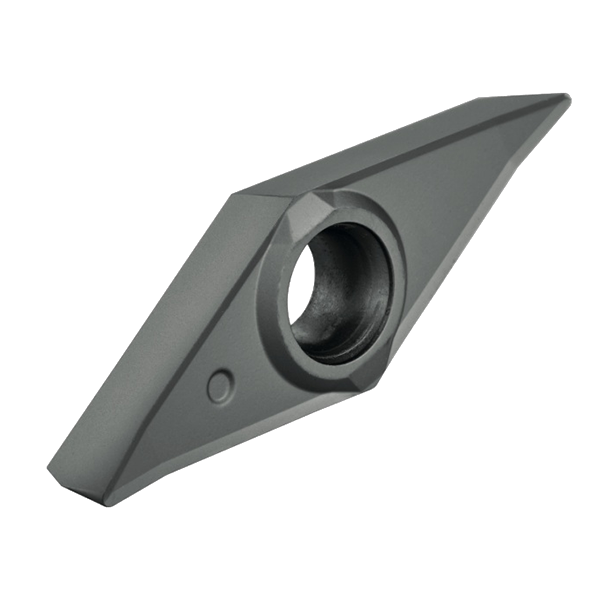
Graphite, Ceramics, and Carbon Fiber are the future, but they are “tool killers.” If you’re still using traditional coating, you’re fighting a losing battle.
Our CVD (Chemical Vapor Deposition) Diamond Coating creates a real crystalline diamond layer on the carbide substrate. This isn’t just a “finish”—it’s a shield.
Why top distributors choose our CVD series:
1.Ultra-Low Friction: Prevents chip welding and heat buildup.
2.Extreme Abrasion Resistance: Maintains sharp cutting edges $20 \times$ longer.
3.Surface Finish: Mirror-like results on the workpiece, zero secondary polishing needed.