
Nullam dignissim, ante scelerisque the is euismod fermentum odio sem semper the is erat, a feugiat leo urna eget eros. Duis Aenean a imperdiet risus.
Nullam dignissim, ante scelerisque the is euismod fermentum odio sem semper the is erat, a feugiat leo urna eget eros. Duis Aenean a imperdiet risus.
 author
The tooling issue with carbon fiber reinforced polymer (CFRP) parts is that they are light, strong and difficult to machine consistently. The fibers in the part can abrade a cutting edge and the part’s resin and laminate structure can pull fibers from the part as the tooling exits. A tooling cutter that looks sharp at the start of its shift can deteriorate in as little as a short part-running shift and be altering hole sizes and reducing edge quality and increasing trim loads.
The choice of diamond coated tools for CFRP work should start with the relevant part features and desired failure behavior. Drilling, edge cutting, slotting and forming of pockets all have different optical properties with respect to cutting edge sharpness, tool stiffness, removal of chips and utilization of the diamond coating. At TSHZ CVD diamond coated cutting tools as well as special geometries for abrasive composite materials are developed.

Carbon fibers in CFRP are hard and abrasive and embedded in a polymer matrix. Depending on the laminate composition of a woven or multidirectional laminate the fibers are running in different directions. When using a sharp cutting edge the resin in front of the edge softens due to the heat and the edge penetrates into the laminate. A blunt edge on the other hand pushes the laminate before it cuts into it.
Examples of typical damages are pull-out of fibers, fraying, delamination, burrs and oversized or tapered holes. Wear and tear of the cutting edges also changes the cutting geometry. In a production cell this can result in additional checks, manual deburring and rejected parts before a tool failure is obvious.
CVD diamond is grown on a carbide or ceramic substrate using chemical vapor deposition. CVD diamond has a hardness of 9,000–10,000 HV, a friction coefficient of approximately 0.05–0.1, and high thermal conductivity. These properties help the cutting edge resist abrasive wear and transfer heat away from the cutting zone.
We must start to treat coatings as part of a tool and not as a ‘universal solution’ to overcome geometry deficiencies. A very hard coating on an edge of poor geometry, with incorrect rake, incorrect point shape or even wrong run-out, will still cause serious damage to a laminate. CVD coatings are particularly useful when working with very abrasive materials and require a very sharp edge to set up and run for long.
For drilling, measure finished diameter, stack height, entry and exit condition and any required surface characteristics. Using a short and stiff drill is important to minimize runout. A point and flute design should be used to clear chips off the laminate surface without rubbing. Record the same amount of detail when inspecting the hole for damage after drilling as was recorded for the entry condition, as delamination often begins where the hole was least supported.
The CVD diamond coated cutting inserts page shows TSHZ’s broader superhard tool direction for non-ferrous and abrasive materials. For a CFRP drill or a custom micro-tool, send the laminate layup, hole size, thickness and current defect so the geometry can be matched to the job.
Trimming needs an edge that shears fibers cleanly rather than rubbing them. Choose the shortest workable projection and support the panel close to the cut. A worn router tends to increase dust, heat and edge breakout at the same time. If the part has a visible cosmetic edge, run a controlled trial with the actual layup instead of relying on a catalogue description.
A custom profile can help when the part includes a step, a narrow flange or a non-standard edge. TSHZ’s custom CVD diamond tool service is intended for drawings that cannot be covered by a standard end mill or router.
Slotting places additional stress on the removal of the chips as well as the tool’s rigidity. Attempt to keep the tool’s engagement constant and restrict its length where possible. Check for slotting ‘ditch’ collapse that can lead to dust entrapment. When working with narrow wall pockets, allow for a finishing allowance and complete the final pass with a sharp edge. This pass must not pull the now loose material with it.

When choosing a cutting tool for CFRP first define the diameter, number of flutes, helix, rake angle and length. While more flutes are generally better, the increased number of flutes reduces the space for dust and cutting chips. This factor has to be taken into account when defining the feed as well as the diameter, depth and whether cutting is open or enclosed.
Check tool runout at the tip, clean the holder, and keep the projection as short as the fixture allows. In small diameter work, a few microns of runout will transfer to one flute and cause it to carry most of the cut. This can concentrate heat to a point on that one flute and cause excessive wear even though the coating is fine.
For complex edges, the CVD diamond layer can be controlled within a thickness range of 1–30 μm. For micro-tools, coating uniformity is important because excessive variation can affect the finished tool diameter, flute clearance, and drawing tolerance. It would be helpful to see a drawing of the tool and to know how it will be inspected before a batch is released.
Start with the machine manufacturer’s limits and work from there. Record the spindle speed, feed per tooth, axial and radial depth, air or vacuum extraction and the number of parts completed. Although dry cutting CFRP is acceptable, it is essential to extract dust from the cutting area and from within the machine itself.
Delamination at the exit can be caused by a lack of support of the backing, by the direction of the cutting tool or by the last part of the cut. Frayed fibers at the edge of a workpiece can be caused by a dull edge, incorrect helix or tool rubbing against workpiece. Increasing the cutting speed or feed without first identifying the cause of the defect will only lead to less stable results.
Measure hole diameter or trim width at the start, middle and end of a trial. Take a photo of the entry and exit points of the hole/trim on a photogrid set to the same magnification as before. This will allow you to establish a part quality based replacement action rather than an arbitrary time based one.
Tooling with diamond coating is more expensive than normal carbide. The most relevant cost comparison is cost per good part, i.e. tool cost, cutting time, changeover time, inspection, deburring, scrap etc. The main economic benefits come from longer usable tool life and fewer tool changes. These benefits should be evaluated against actual cutting time, inspection, deburring, scrap, and replacement frequency.
Run the same comparison test with the same laminate and program. A tool that lasts longer but leaves a damaged edge is not cheaper in the long run. A tool that keeps the same trim width and needs less manual repair might even be cheaper than a seemingly cheaper tool with a higher unit price, several times higher even.
Custom geometry is worth discussing when the part has a narrow flange, a stepped edge, a small internal radius, a deep hole or a tolerance that standard tooling cannot hold. Share the material grade, fiber orientation, ply count, thickness, feature drawing, spindle details and the exact defect you are seeing.
TSHZ combines CVD coating with five-axis edge preparation and non-standard tool design. The CFRP and composite machining service is a practical starting point for a drawing review. For a sample or application discussion, use the TSHZ contact page.
They can be suitable for many abrasive CFRP operations, but the laminate, feature and machine still determine the geometry and cutting data. Validate the tool on the production material before a full release.
Use a sharp, rigid tool, keep runout low, support the exit side and control the final part of the cut. Measure both entry and exit quality during the trial.
Regrinding is generally not recommended because it can remove the functional diamond layer and change the designed edge. Replace the tool according to wear, dimensional drift and edge quality.
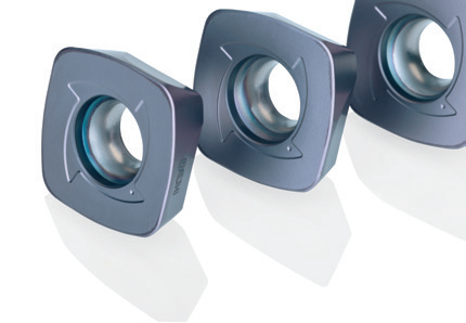
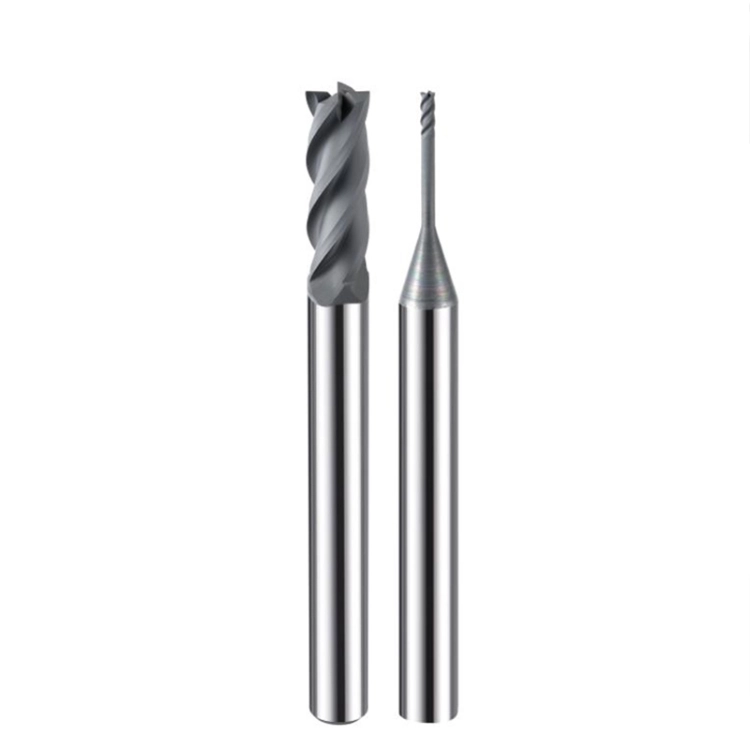
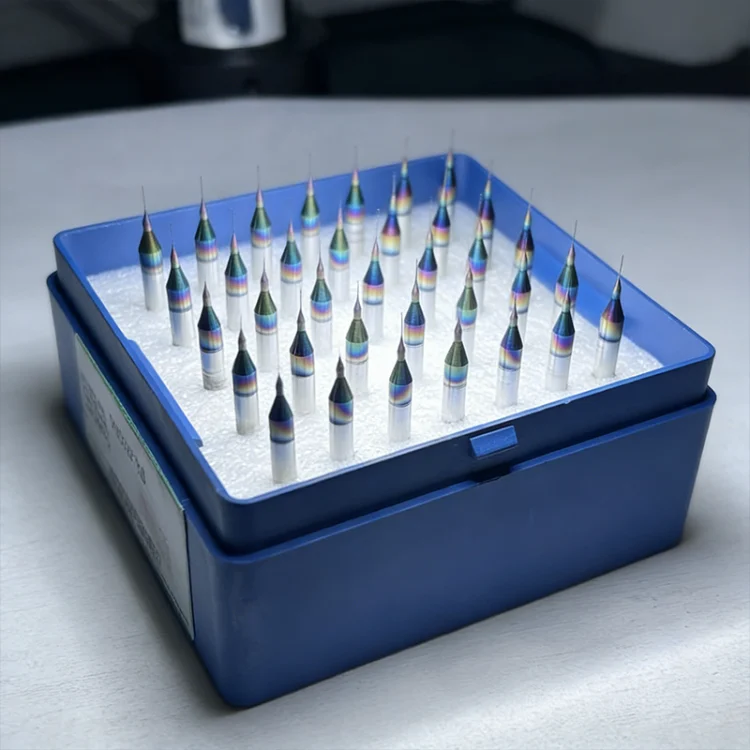
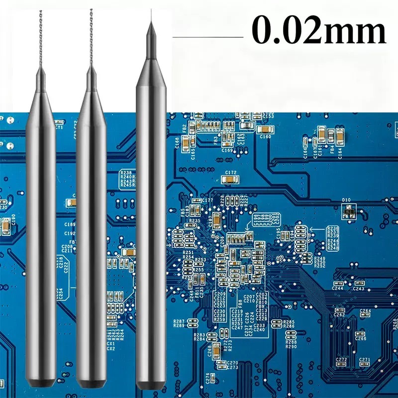
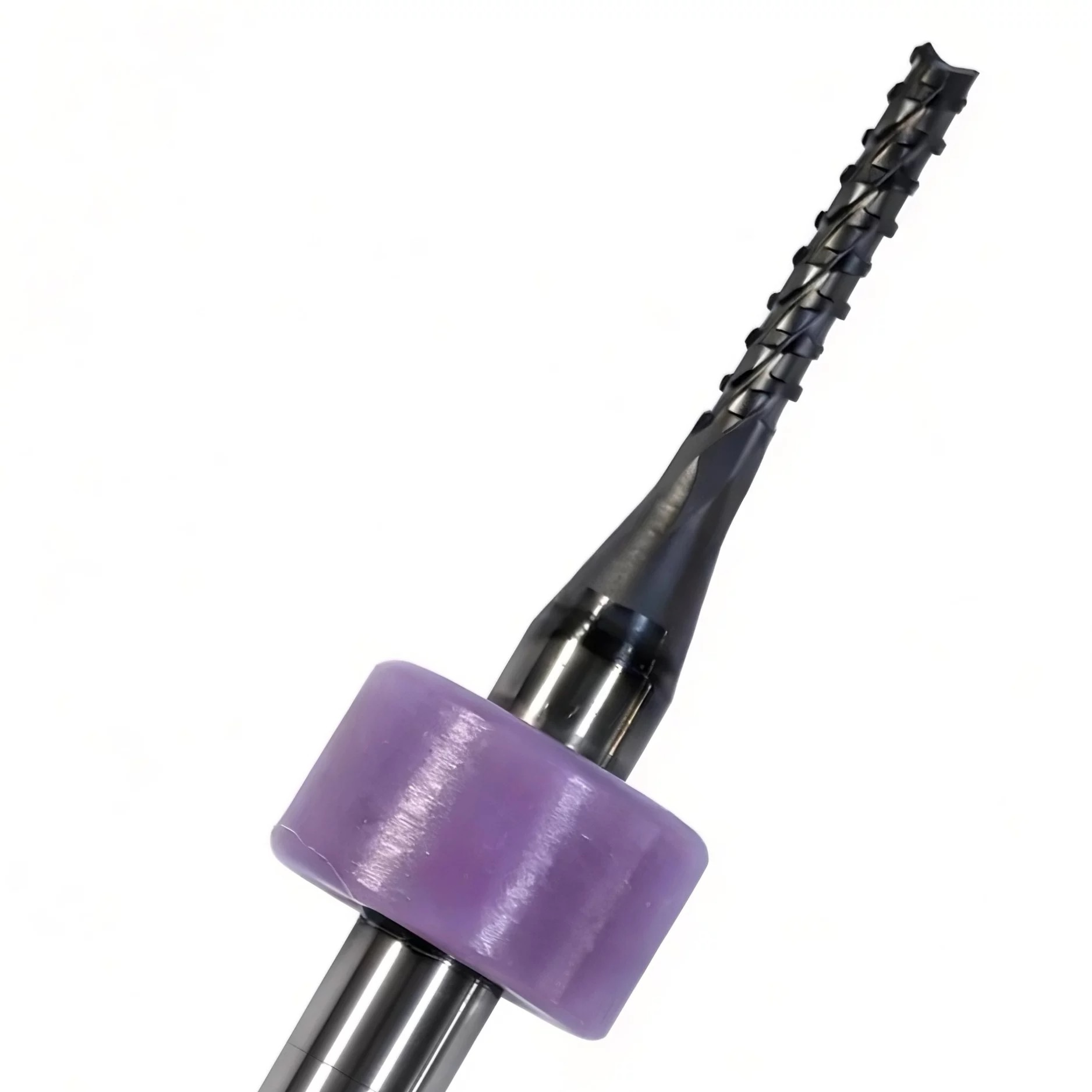
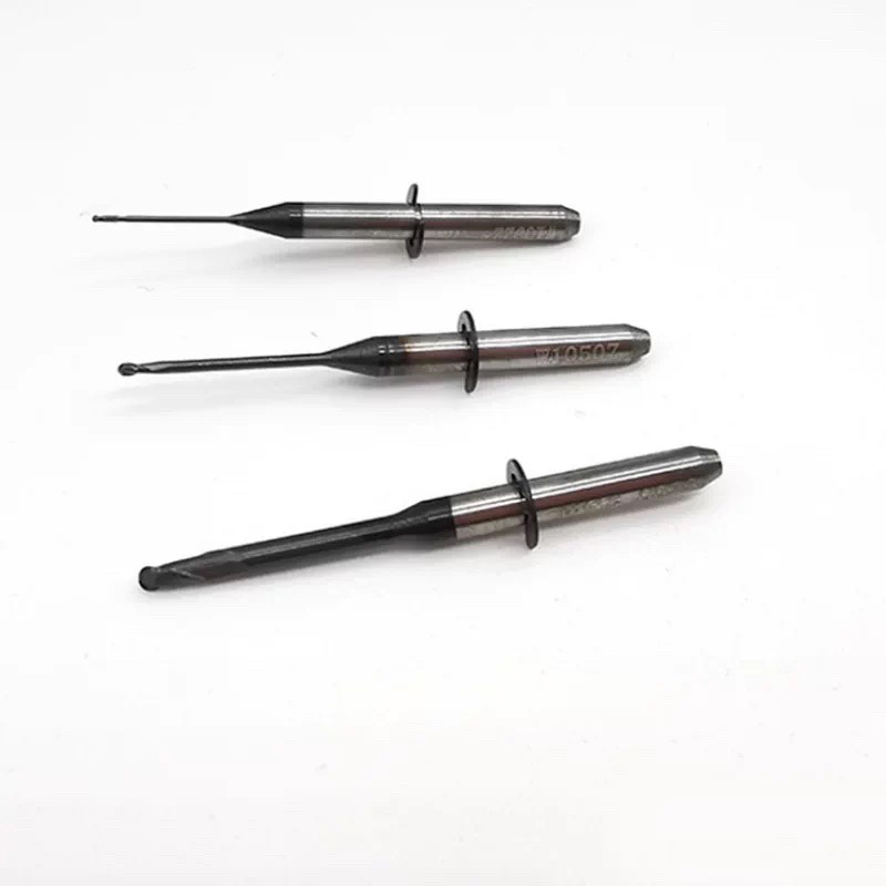
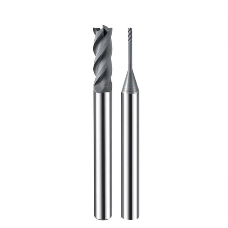
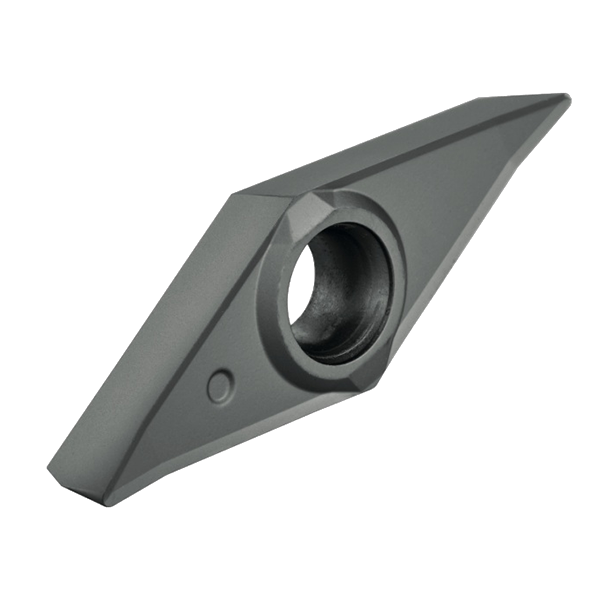
Graphite, Ceramics, and Carbon Fiber are the future, but they are “tool killers.” If you’re still using traditional coating, you’re fighting a losing battle.
Our CVD (Chemical Vapor Deposition) Diamond Coating creates a real crystalline diamond layer on the carbide substrate. This isn’t just a “finish”—it’s a shield.
Why top distributors choose our CVD series:
1.Ultra-Low Friction: Prevents chip welding and heat buildup.
2.Extreme Abrasion Resistance: Maintains sharp cutting edges $20 \times$ longer.
3.Surface Finish: Mirror-like results on the workpiece, zero secondary polishing needed.