
Nullam dignissim, ante scelerisque the is euismod fermentum odio sem semper the is erat, a feugiat leo urna eget eros. Duis Aenean a imperdiet risus.
Nullam dignissim, ante scelerisque the is euismod fermentum odio sem semper the is erat, a feugiat leo urna eget eros. Duis Aenean a imperdiet risus.
 author
A chip at the margin is reason to stop and inspect. It is not, by itself, proof that the bur is finished. Find out when the chip appeared and whether the same problem turns up on comparable jobs. A crown count can tell the lab when to look; the margin inspection tells it whether the work passes.
At a glance: Hold a bur with visible edge damage or unknown history. For an intact, tracked tool, compare repeatable margin inspections with a fresh equivalent bur before setting a replacement point. Keep the blank, toolpath, holder and inspection method stable during that comparison.
These checks concern presintered zirconia milled in a dental lab. Chairside instruments and fully sintered restorations need their own assessment. Keep the bur drawing with the machine record: diameter, reach and runout limits have to match that tool and mill.
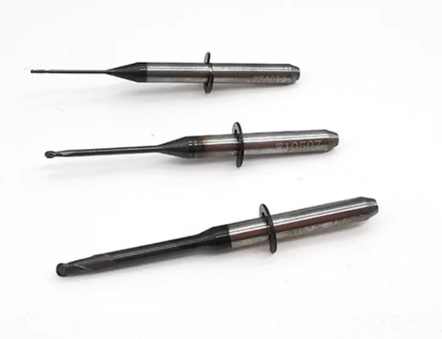
The zirconia milling bur shapes the blank in the dental mill. A damaged edge, or an edge whose condition cannot be checked, takes that bur out of use immediately. If it looks intact, judge it on comparable jobs against the lab’s margin rule. Set the change point from those results rather than from crown count alone.
| Finding | Practical next step |
| Visible edge damage or unknown tool history | Hold the bur and use a traceable replacement for the next job |
| One isolated margin chip | Record the location and check handling, blank, holder and toolpath |
| Similar defects recurring on comparable jobs | Run a controlled comparison against a fresh equivalent bur |
| Repeat samples miss the lab’s acceptance rule | Set a replacement point before the next scheduled production run |
This separates an immediate tool hold from a planned life limit. One defect cannot establish that the bur caused it. The published crown-milling study links repeated use to changing marginal results in one system, without validating a replacement count for other systems.
Start with timing: was the chip visible on unloading, after separation, after cleaning or only after handling? Mark its location before polishing. A nick at the thin cervical margin calls for a different investigation than roughness across several surfaces. Keep the job number with the restoration so the defect remains traceable to the blank and tool record.
Presintered zirconia wears cutting edges. The first visible effect may be at the thin cervical margin, while the rest of the restoration still looks acceptable. But a chip in that spot can also follow a blank, toolpath, holder or handling problem. Check those before assigning the cause to the bur.
A laboratory study milled 56 zirconia crowns with one tungsten-carbide bur set. Mean marginal gap increased from 34.78 μm in the first group to 99.69 μm in the last; the final two groups did not differ significantly. The system warned for replacement after crown 27. The result supports tracking tool use alongside margin quality. It does not set a service interval for another bur, machine or material. See the zirconia bur-wear study.
If two consecutive crowns show a similar defect at the same margin location, compare the tool and setup before calling the bur worn. If the first chipped during separation and the next was clean, review handling before retiring the bur. Marginal discrepancy reflects the full milling and handling process; the cited study isolates only part of it.
Keep the restoration tied to its job number and bur ID. Photograph the defect in context and at the lab’s standard magnification, then record pass or hold before repair. Polishing removes the original evidence needed to decide whether the margin met the requirement.
A recognized and affixed marginal restoration of the same blank type and design can serve as a comparison for examining in comparable lighting, magnification. Log if the difference is limited to margin or elsewhere and keep that in log along with reference result. Make a note of whether the diff is limited to margin or existing elsewhere and log it with reference result.
Dust that is leftover on the edge can result in heat being added to beaker. Use the same mill and maintenance procedures to address both preventing loss of an extraction path as well as checking burrs. When that process does not clarify the cleaning approach, ask first with suppliers of equipment or instruments; damaged coating would render this next comparison to be indecipherable. If that process does not clarify how you clean it, ask the provider of equipment or tool first; a damaged coating would cause malfunction in further comparisons.
The next margin may benefit from a new bur or altering the feed. But, if the holder sharpens and milling in strategy also changes, then now it is unknown what helped. The complete setup, make a note of all the before playing with it and used that to compare against next restoration. Take note of the setup before making any changes to it — you may then use whatever restoration follows as a baseline.
Match the bur in the spindle to the mill’s tool position and software record, then check seating by the equipment maker’s method. Record runout against that mill’s specified limit beside the model or individual tool ID; a borrowed tolerance may not apply.
A nice-looking edge is no indication of service history. If the bur has transitioned from one machine to another, or if no related date for when it was first used is known: Set as untracked Retrieve the record or an identifiable substitute before utilizing it as a basis for release. Rebuild from the record or a location-limit lower back trail earlier than considering it an account to release.
For a useful comparison, the lab needs an approved trial sample and a clear margin criterion first. Run the suspect bur and a fresh equivalent on the same blank type, design and path, then inspect them the same way. If the job forces another change, write that down too. The NIST explanation of experimental design makes the logic clear: choose the factor to change and measure a defined response. For example, if the suspect bur leaves chips at the marked margin while a fresh equivalent does not, check whether the holder, blank and path stayed the same. If another variable changed, repeat the comparison before setting a replacement point. A shop trial narrows the question; it does not model every interaction in milling.
Keep both restorations and their notes. A cleaner margin from the fresh bur under controlled conditions supports replacement, whereas the same defect on both samples directs attention back to the blank, toolpath, setup or handling. Let the laboratory’s quality process decide whether that single comparison needs replication.
A replacement point is the agreed limit at which a laboratory withdraws a tracked bur before routine jobs fail its margin criterion. It is specific to the workflow, not a universal service interval; a fixed crown count cannot be transferred across mills without validation. The NIST measurement-process guide explains why reference conditions, variability and collection method matter when interpreting a change in measured results.
Before the trial, define an acceptable margin from the restoration drawing, customer requirement and laboratory procedure. Select a repeatable inspection location and photograph it under consistent conditions, retaining rejected samples in the log. For example, record a failing cervical margin separately when other surfaces remain consistent; a list limited to accepted restorations conceals when the process began to drift.
Tool life is the work completed between first use and a defined failure point. One workflow may track restorations; another may track cutting length. Record blank, design and toolpath beside the number because a count from different operating conditions cannot predict the next run.
| Log item | Record |
| Tool | Model, identifier and first-use date if known |
| Job | Blank type, restoration design and milling strategy |
| Output | Crown count or cutting length since first use |
| Inspection | Location, image and acceptance decision |
| Action | Continue, compare, investigate or replace |
Set the change point before comparable jobs begin to miss the acceptance rule, allowing production to replace the bur before a rejected restoration forces an unplanned stop. Revalidate the limit after a change in blank, design or milling strategy.

Remove an unidentified bur from rotation until its history is recovered or a traceable replacement is approved. A status label prevents the next operator from inferring service history from an intact-looking edge.
Give the supplier the mill, tool position, cutting diameter, working reach and overall length. Compare the drawing with the machine’s approved tool list. A nominal 4 mm shank does not, on its own, establish a fit.
TSHZ supplies standard-size diamond-coated tools and discusses non-standard sizes, including diamond-coated dental burs. Its CVD process grows a high-purity polycrystalline diamond film on carbide. For a replacement, put the machine requirements beside the product details in the inquiry. “Diamond bur” does not tell the supplier enough to check a fit.
The RN models listed below have a 50 mm overall length and a nominal 4 mm shank. Their cutting diameters differ, so use the individual model drawing to choose among them.
| Model | Cutting diameter (mm) | Overall length L3 (mm) | Nominal shank D3 (mm) |
| RN-040 | 0.4 | 50 | 4 |
| RN-060 | 0.6 | 50 | 4 |
| RN-080 | 0.8 | 50 | 4 |
| RN-100 | 1.0 | 50 | 4 |
| RN-200 | 2.0 | 50 | 4 |
| RN-100L | 1.0 | 50 | 4 |
| RN-200L | 2.0 | 50 | 4 |
Confirm reach, cutting diameter and the mill’s assigned tool position as well as shank compatibility before approving the replacement.
The CVD diamond coated dental burs page is the sensible starting point for a zirconia replacement. Compare the drawing with the mill’s tool requirements and the actual operation. Confirm the exact model with the supplier before ordering a production quantity.
For a separate look at how cutter form and coating relate to machining accuracy, see TSHZ’s tool geometry and coating overview. Use it as general context; the dental-bur drawing still governs the replacement decision.
Ask the supplier before sharpening a diamond-coated bur. Regrinding may damage the coating and expose the lower-hardness substrate. If refurbishment is approved, start a separate usage record for that tool; it is not a new bur.
For a replacement inquiry, send the machine model and blank ID with the bur drawing, images taken before correction, usage log and any fresh-bur comparison. State which margin requirement failed. The crown count alone gives the supplier too little to recommend a model.
Send the drawing and sample details through the TSHZ contact page when you are ready to check a model. For company background, visit about us.
No single crown count fits every lab. Set an inspection trigger and replacement point for the blank, bur, restoration design and strategy actually in use. Recheck it when those conditions change. A supplier estimate can frame a trial; the lab’s acceptance rule remains the release standard.
Coating does not remove margin inspection or tool tracking. It describes the surface on the bur. The crown and the usage record show how that bur is behaving in the lab’s process.
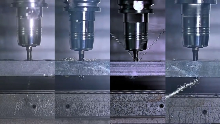
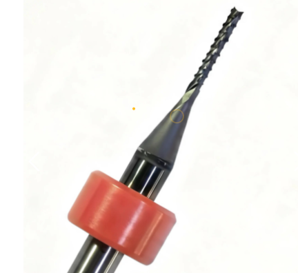
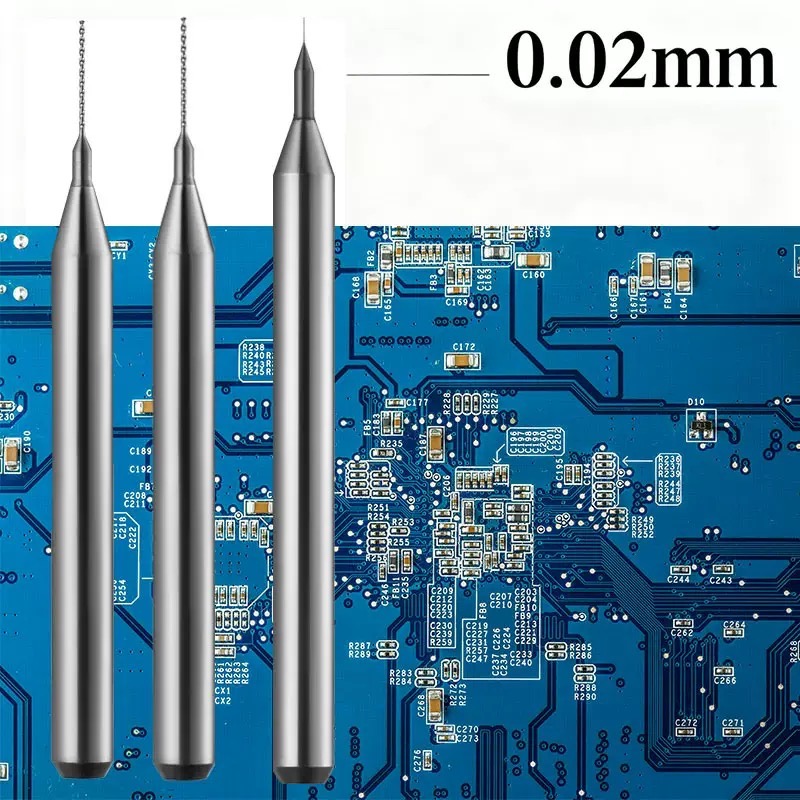
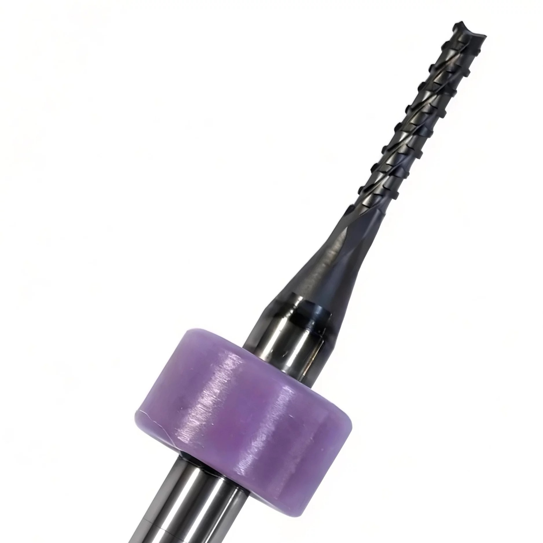
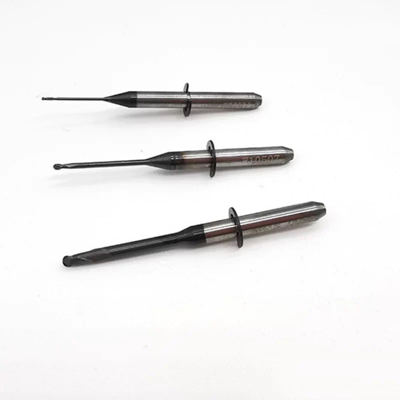
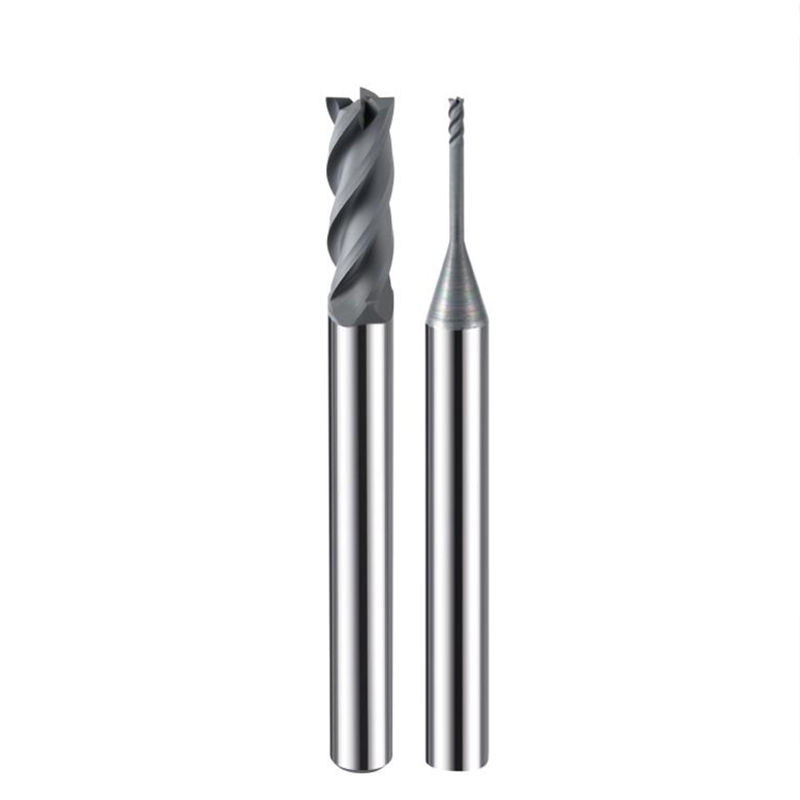
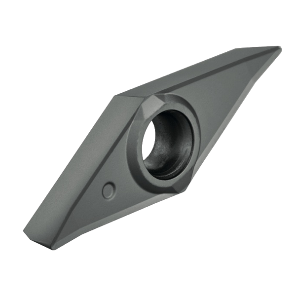
Graphite, Ceramics, and Carbon Fiber are the future, but they are “tool killers.” If you’re still using traditional coating, you’re fighting a losing battle.
Our CVD (Chemical Vapor Deposition) Diamond Coating creates a real crystalline diamond layer on the carbide substrate. This isn’t just a “finish”—it’s a shield.
Why top distributors choose our CVD series:
1.Ultra-Low Friction: Prevents chip welding and heat buildup.
2.Extreme Abrasion Resistance: Maintains sharp cutting edges $20 \times$ longer.
3.Surface Finish: Mirror-like results on the workpiece, zero secondary polishing needed.