
Nullam dignissim, ante scelerisque the is euismod fermentum odio sem semper the is erat, a feugiat leo urna eget eros. Duis Aenean a imperdiet risus.
Nullam dignissim, ante scelerisque the is euismod fermentum odio sem semper the is erat, a feugiat leo urna eget eros. Duis Aenean a imperdiet risus.
 author
PCB drilling looks simple until hole quality starts moving from lot to lot. Glass fiber cuts the edge, resin holds heat around the hole, and copper foil can pull or deform when a worn drill exits the board. The result is familiar to PCB engineers: burrs, smear, nail head, hole-size drift and more frequent tool changes.
For HDI and multilayer production, the right PCB diamond drill bits should be selected from the finished hole, board stack, material mix and required life together. A CVD diamond micro drill is useful when abrasive laminate, tight hole tolerance or long unattended cycles make ordinary carbide too costly. TSHZ supplies CVD diamond-coated PCB drills and custom superhard cutting tools for these applications.
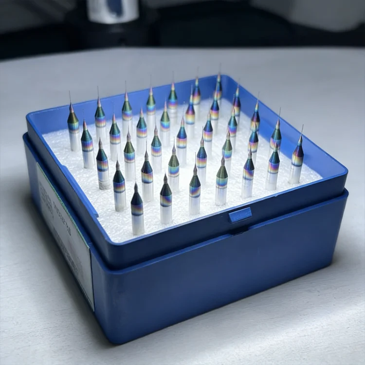
FR-4 and related laminates combine glass fiber, resin and copper. High-frequency boards may also contain ceramic fillers, while HDI structures add small features and tighter positional requirements. The glass and ceramic phases act as abrasives. Resin can soften when heat stays in the hole, and copper can stretch at the entrance or exit.
Tool wear changes more than the cutting edge. As the diameter and point geometry change, the hole may become oversized or wander from its intended position. A rough hole wall can also create downstream plating and reliability problems. This is why drill selection should begin with the board material and finished-hole requirement rather than with a catalog price.
CVD diamond is grown on a suitable carbide substrate through chemical vapor deposition. Its high hardness resists the abrasive action of glass fiber and ceramic filler. TSHZ describes its CVD diamond coating with hardness around 9,000 HV and a low friction coefficient, both of which help the edge stay stable during repeated drilling.
The practical benefit is consistency. A sharp edge produces cleaner entry and exit conditions, while lower friction helps control heat and chip movement. TSHZ’s PCB Diamond Drill Bit page lists drills for general multilayer and HDI boards, FR-4, CEM-1 and eco-friendly boards, with a stated diameter range of 0.1–3.175 mm. The same page presents a service-life claim of more than 3,000 holes per bit for the latest PCB boards. Treat that figure as an application reference, because actual life still depends on laminate, stack height, machine condition and drilling parameters.
The drill diameter should be calculated from the finished hole, copper plating allowance and the process window. A nominal hole number on a drawing is not always the final drill size. If the hole will be plated, the drill normally needs compensation for the copper that will be added later.
For holes above about 0.5 mm, the TSHZ knowledge base gives a practical compensation range of roughly 0.03–0.05 mm. Use that as a starting point, then confirm it against the board supplier’s stack-up, plating thickness and inspection data. For smaller HDI holes, do not copy the same compensation blindly. Small changes in runout, point geometry and board support have a larger effect.
Before ordering, record:
This information gives the tool supplier enough context to recommend a diameter instead of simply matching a nominal number.
HDI drilling needs a balance between clearance and stiffness. A flute must remove chips without leaving too little material behind the cutting edge. A longer drill may reach a tall stack, but unnecessary length increases deflection and runout. The safer rule is to use the shortest total length that clears the fixture and board stack.
TSHZ provides a PCB Diamond Tools Series for different PCB drilling and milling requirements. Its site describes the PCB drill bit as having chip-removal and hole-roughness benefits for multilayer and HDI boards. The knowledge base also separates typical selection logic: a UC-style series for dense micro-hole work, a standard series for general FR-4 and CEM boards, and a larger-diameter series for thick boards. Confirm the exact model and dimensions before production because a series name alone does not replace a tool drawing.
Shorter length improves rigidity, but it cannot compensate for a worn collet or excessive stack height. Check runout at the tool tip, keep the board supported, and avoid adding layers simply to increase output per setup. The extra stack may raise positional error and make a small drill more likely to break.
Drill quality comes from the tool and the process. A sharp, wear-resistant edge helps, but the machine still needs a suitable feed, speed and withdrawal condition. If the entry side shows burr, review the entry board and cutting conditions. If the exit side shows burr or copper deformation, inspect the backing board and withdrawal behavior.
Nail head is usually associated with copper deformation during exit or with a drill that has lost its edge. The TSHZ knowledge base recommends keeping nail head below 50 μm as a practical quality target and identifies sharp diamond-coated drills as one way to reduce the defect. Use microscopy and hole-wall inspection to establish a replacement rule instead of waiting for visible failure.
If smear appears, look for heat, resin softening and chip evacuation problems. Changing to a harder drill alone will not correct a process that traps heat in the hole. Review the stack, backing support, feed and cleaning routine together.
A diamond-coated drill normally costs more than an uncoated carbide drill. The useful comparison is cost per hole: tool price divided by usable holes, plus changeover time, inspection, scrap and rework. A higher-priced drill can be the lower-cost choice when it holds diameter longer and reduces unplanned stops.
This calculation also makes trials easier. Run the same board material with the same hole size and record hole count, diameter drift, burr, nail head and changeover minutes. Compare the full result rather than one early sample.
TSHZ is a practical candidate when your production involves abrasive glass-fiber laminate, HDI or multilayer boards, small holes, repeated quality drift or high tool-change frequency. The company combines CVD diamond coating with custom tool geometry and lists PCB micro drills, milling cutters and other superhard cutting tools in its product range. The PCB application page gives a broader view of the board materials and machining problems addressed by its tooling.
Send the finished-hole size, board stack, laminate type, spindle information and current failure mode when requesting a recommendation. TSHZ can then match the drill geometry and coating approach to the actual process instead of treating every PCB as the same job. For a drawing review or sample discussion, use the verified contact page.
Life depends on board material, hole size, stack height, machine runout and parameters. TSHZ lists more than 3,000 holes per bit for the latest PCB boards as an application reference. Validate the result with your own board and inspection method.
Regrinding is generally not recommended for coated drills because it can remove the diamond layer and expose the lower-hardness substrate. Ask the supplier about replacement and inspection criteria instead.
Start with finished hole size and plating compensation, then check the laminate, stack height, shortest workable tool length, chip clearance and spindle runout. For very small holes, confirm the exact model drawing and trial data before releasing a batch.
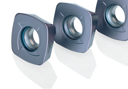
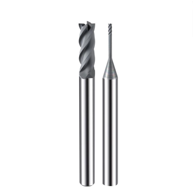
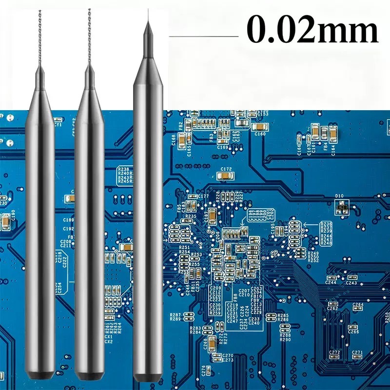
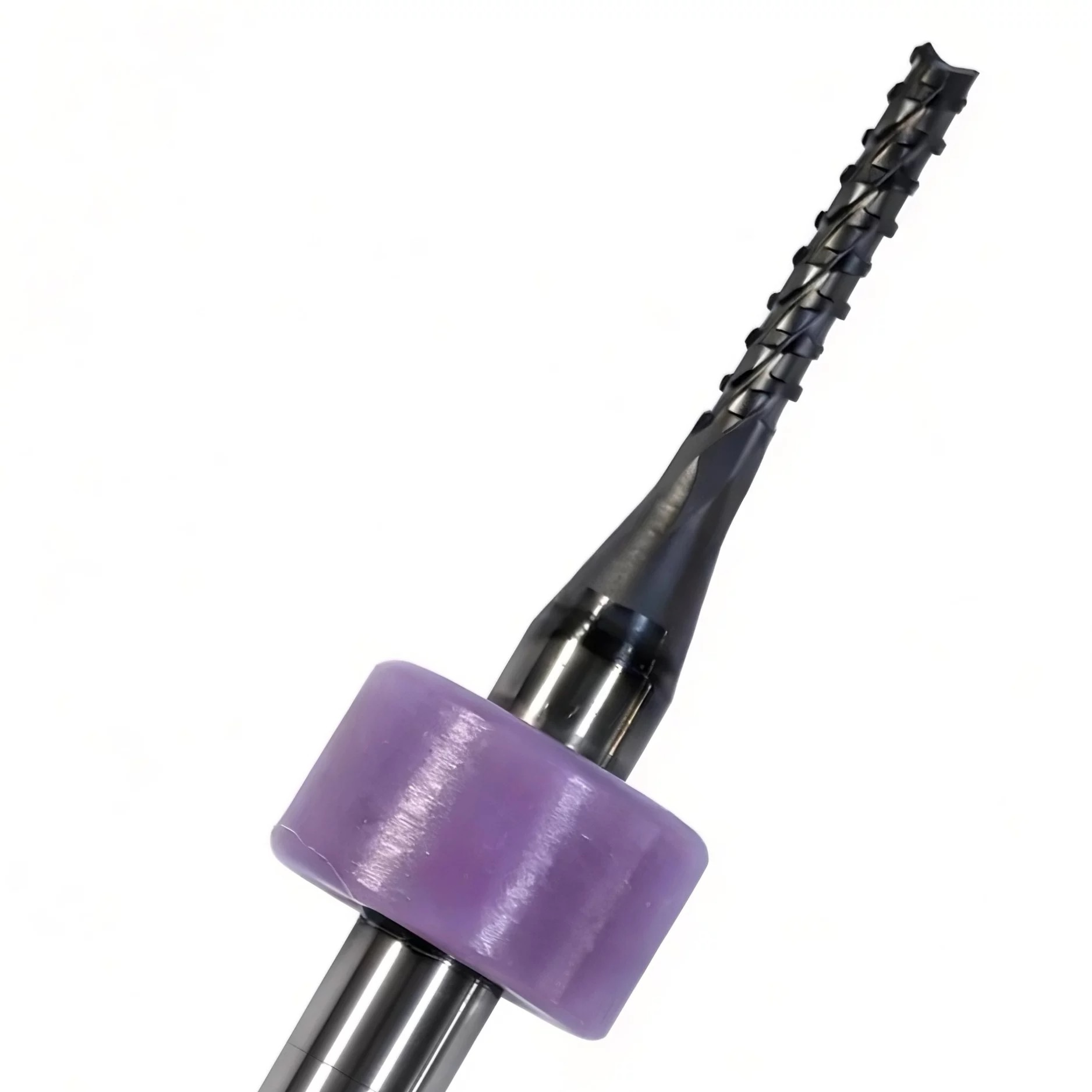
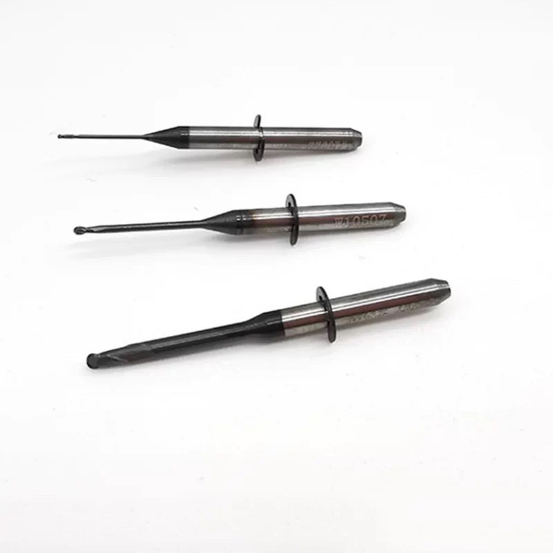
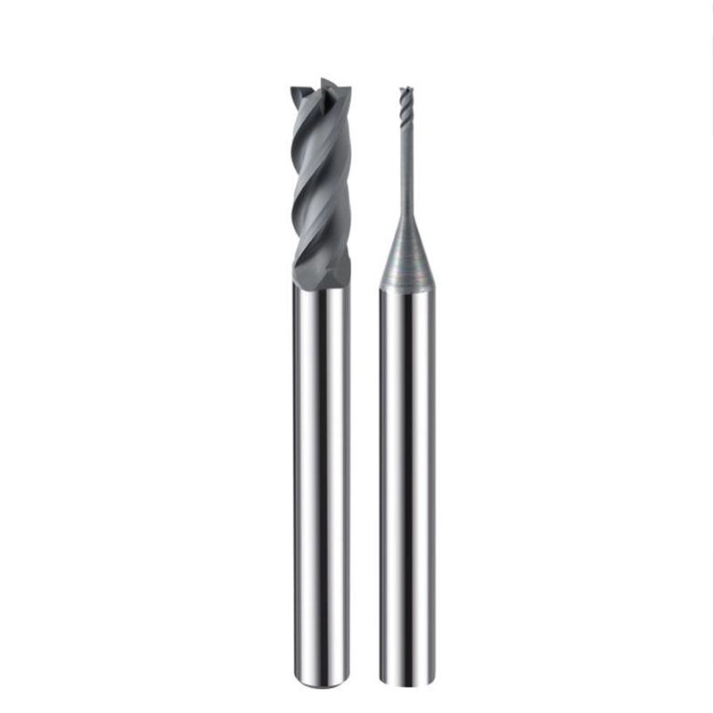
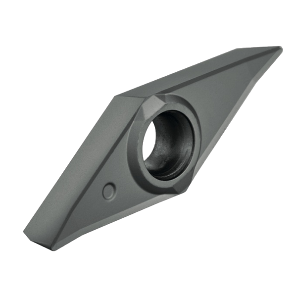
Graphite, Ceramics, and Carbon Fiber are the future, but they are “tool killers.” If you’re still using traditional coating, you’re fighting a losing battle.
Our CVD (Chemical Vapor Deposition) Diamond Coating creates a real crystalline diamond layer on the carbide substrate. This isn’t just a “finish”—it’s a shield.
Why top distributors choose our CVD series:
1.Ultra-Low Friction: Prevents chip welding and heat buildup.
2.Extreme Abrasion Resistance: Maintains sharp cutting edges $20 \times$ longer.
3.Surface Finish: Mirror-like results on the workpiece, zero secondary polishing needed.