Sin dignidad, ante el scelerisque el odio es euismod fermentum sem semper the is erat, a feugiat leo urna eget eros. Duis Enean un corte de pelo para reír.

Nail-Head Defects in HDI Drilling: A Practical Fault-Isolation Guide

  • Nail-Head Defects in HDI Drilling: A Practical Fault-Isolation Guide autor
  • 11th noviembre 2026

The first clue may be a rejected cross-section, not a rough-looking hole. Copper at an inner layer has bent or spread, although the board surface looks ordinary. In HDI and multilayer production, that is a different investigation from chasing a visible burr. Keep the suspect panel, record its place in the drill stack, and examine a section before changing the setup. Otherwise an apparent improvement after a tool change may simply reflect a different panel or a different point in the drill’s life.
Nail-Head Defects in HDI Drilling A Practical Fault-Isolation Guide

In FR-4, the edge passes through glass fiber, resin, and copper. Glass is abrasive, resin retains heat, and copper can deform rather than break cleanly. TSHZ identifies worn edges and copper pulled during drill withdrawal as nail-head mechanisms in PCB work. A worn drill may also leave rough walls or drift from its intended hole position. The inspection sheet should have separate entries for those faults. “Bad holes” gives the next shift almost nothing to work with.

Confirm the defect before changing the drill

Where to inspect a cross-section

Nail heading is deformation of copper at the inner-layer interface visible in a prepared hole cross-section. Save an image of the whole hole as well as a close view of the affected layer. Label the layer, panel, and drilling sequence on the image. A nearby acceptable hole from the same setup is a useful reference. Without it, “rough” or “pulled” can mean different things to the drilling and quality teams.

A number written into a supplier FAQ is not the acceptance limit for every PCB. Use the drawing and the plant’s inspection method. If the copper shape is borderline, identify the measurement points and retain the prepared section. Preparation damage can confuse the reading; section another hole if necessary. Changing feed before the feature is agreed upon wastes a trial.

Separate nail heading, burrs, and resin smear

An entry or exit burr sits at the board surface. Nail heading sits at buried copper. Resin smear is different again: softened resin can coat the wall and interfere with exposed copper. The University of Maryland CALCE explanation of resin smear helps identify that wall condition. Several faults may be present on one panel. Give each one its own photograph and description.

Write a separate note for the surface burr and the buried copper. Add wall condition and hole position. Which panel was cut? A technician repeating the inspection tomorrow should be able to find the same feature without guessing. If a trial makes the entrance clean but leaves the inner layer distorted, the work is not finished.

Record the pattern across the panel and stack

Top versus lower panels

“Sample from the stack” is a poor label. Number the panels from top to bottom and put that number on each cross-section. An upper-panel failure that appears immediately may call for a fresh-tool or entry check; gradual deterioration down the stack points elsewhere. TSHZ’s PCB guidance warns that adding layers to a stack increases drill deflection risk and can reduce positional accuracy, especially with small diameters. A short drill is stiffer and less prone to wandering than an unnecessarily long one. Check both dimensions against the actual setup before deciding that nail heading is caused by wear alone.

The drilling traveler should identify entry and backing materials and how the panels were held. Measure actual drilling depth. Is the flute long enough to clear the full stack? Is the exposed drill longer than necessary? If coordinate data exist, compare hole position on upper and lower panels. A trend down the stack merits a setup check, even when edge wear is also visible.

Early holes versus late holes

Pick holes from the start and late part of the same drill run. Section them in the same way. A late sample with worse copper deformation is useful only if its laminate, hole size, and stack are known. Ask whether the wall has also become rougher or the hole position has moved. TSHZ recommends looking at hole-wall quality and visible edge wear when deciding when to replace a PCB micro drill. Keep the used edge with its sample record, rather than a tray of unlabelled drills.

The first holes are defective. That points to the setup before a wear-life discussion: was the specified drill fitted, did it seat correctly, what was the runout, and which entry and backing materials were used? Record feed, speed, and stack height. A defect that appears only much later has a different timeline; pull that drill and inspect its edge and flutes. Treating the two timelines as one problem makes both harder to solve.

Test the likely causes in order

Edge condition and replacement timing

Glass fiber in FR-4 abrades the edge; copper can be drawn into a deformed shape as the edge loses cutting ability or during withdrawal. In HDI drilling, carbide drill wear can coincide with nail heading, rough hole walls, and positional drift. That combination is a reason to examine the point and cutting edges, then match the edge photograph to the holes drilled with that tool. It is not a guarantee that another factory will see the symptoms in the same order.

Keep the first acceptable section and the last one before the defect limit is crossed. Put the corresponding edge images beside them. This gives purchasing and production a replacement point tied to their board, rather than a hole-count figure borrowed from another laminate. TSHZ also advises against routine regrinding of a diamond-coated micro drill because grinding can remove the coating and alter the edge geometry. If regrinding is attempted, its output belongs in a separate trial record.

Chip evacuation and heat

The hole contains a difficult mix: abrasive glass fiber, insulating resin, and ductile copper. Resin’s poor heat conduction can leave local heat around a drill, while packed chips change contact at the edge. Pull the suspect drill and inspect the flutes for loading. Section a nearby hole to check for smear. Heat and chip removal may matter even if nail heading is the rejected feature. The Arlon drilling-defects technical note gives a useful reference for reading drill wear alongside cutting conditions.

There is a temptation to change everything when scrap is rising. Resist it for the short diagnostic run. Change feed, or stack, or tool type, then compare the same panel position. Four simultaneous changes may produce a good section without showing which one helped. The withdrawal setting belongs on the sheet as well; the copper can be pulled on the way out.

Stack support, length, and machine condition

Measure runout at the fitted tool, not merely at an empty spindle. Check seating, spindle condition, and whether the stack lies flat. A short total length improves rigidity for PCB drilling; too many stacked panels increase deflection risk for small drills. That is a direction for testing, not a universal stack count. If one machine produces the damage and another does not, investigate the machine before assuming that the drill design is wrong.

On lower panels, look at the backing and the withdrawal move. On one suspect spindle, check the spindle. It sounds basic, yet a tool trial often arrives with no record of which copper layer was rejected. Attach two labelled sections to each change request: one before and one after. They will settle more than a note saying “new drill helped.”

When a different drill is the useful experiment

TS-A01UC for HDI micro-hole trials

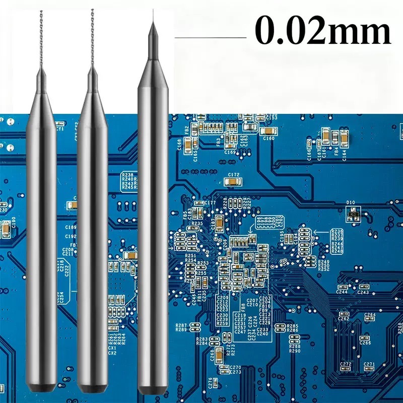
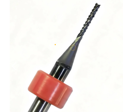
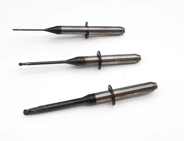
TSHZ offers a Broca de diamante para PCB range for general multilayer and HDI boards. Its TS-A01UC micro drill is specified for HDI and multilayer work; the UC flute is intended to improve chip evacuation in dense small-hole drilling. It is worth trialling when worn edges or chip-packed flutes are part of the defect record. A fresh coated drill cannot compensate for a loose stack or a spindle running out.

Specify diameter and effective length against the finished-hole requirement, plating allowance, and actual stack. TSHZ also offers TS-A02 ST for standard FR-4/CEM work and TS-A03 for larger-diameter or thicker-board drilling. When comparing series, record the geometry and length as well as the coating; more than one property may have changed. The separate HDI and multilayer drill comparison covers that selection decision in more detail.

PCB diamond drill bit

Compare on the same board and inspection method

Run the candidate against the same laminate, stack, diameter, machine, and sectioning method as the current drill. Sample near the beginning and end of each tool run. Record the buried copper, surface burr, wall, hole position, and edge. An improved entrance with unchanged inner-layer distortion is an entrance improvement, not a nail-head solution. Extend the comparison far enough into the run to see whether the result holds.

What to send with a tooling inquiry

An inquiry is easier to answer when it includes the laminate and board build, copper-layer arrangement, finished-hole target, current drill diameter and length, total stack, machine, and spindle. Attach edge and cross-section images labelled with panel position and hole count. Include feed, speed, withdrawal settings, and the board’s own acceptance requirement. TSHZ’s Página de aplicación de PCB covers the board-material context. The labelled samples show the precise failure under discussion.

Preguntas frecuentes

Is every copper burr a nail head?

No. Surface burrs appear at entry or exit. Nail heading is evaluated at an inner copper layer in a prepared hole cross-section. Report both if both are present.

Does a diamond-coated drill remove the need to check the stack?

No. The drill edge, flute, length, stack support, runout, and withdrawal condition all affect the result. A coated tool trial is most informative after the defect pattern has been documented.

What should trigger a drill replacement review?

A change in hole-wall quality, nail-heading trend, roughness, positional accuracy, or visible cutting-edge wear is a reason to review the replacement interval. Use the plant’s own inspection requirement and board construction rather than a copied universal hole count.
Etiquetas:

Tabla de contenido

Preguntas frecuentes

El precio es lo que pagas, el costo es lo que pierdes. Una herramienta de $15 que detiene tu máquina de $200,000 cada 2 horas es lo más caro de tu taller. Nuestra herramienta CVD cuesta más porque te proporciona 40 horas de funcionamiento ininterrumpido del husillo. ¿Cuál te ahorra más al final del mes?
Me encantan los escépticos; suelen convertirse en nuestros mejores clientes. En grafito G5 o aluminio con 18 % de silicio, el carburo estándar se desgasta en minutos. Nuestra capa cristalina de diamante HV$ de $8000 ignora literalmente ese desgaste. No solo lo afirmamos; tenemos los informes de pruebas de microdesgaste que lo demuestran. ¿Quieres ver el video comparativo?
Un momento. Me encantaría venderte una herramienta, pero el diamante y el hierro son incompatibles a altas temperaturas (debido a su afinidad química). Para acero, usa nuestra serie AlTiN. Pero si vas a cortar grafito, CFRP o cerámica, nuestro CVD es indiscutiblemente el mejor. Vendemos soluciones, no solo metal.
Esa es la diferencia entre el DLC (carbono tipo diamante) y el CVD auténtico. La mayoría de las herramientas de "diamante" baratas son solo películas delgadas. Nuestro CVD se cultiva químicamente sobre el sustrato de carburo. No se queda en la superficie; forma parte de la herramienta. Sin desprendimiento, solo corte puro.
De hecho, lo mejora. Gracias a que la capa de diamante es ultrasuave y el filo se mantiene afilado 20 veces más tiempo, se evita el efecto de "desgarro" propio de una herramienta desafilada. Se obtiene un acabado similar al de un espejo en la pieza número 100, igual que en la primera.
No les vendas una herramienta; véndeles "capacidad de máquina". Diles a tus clientes: "¿Prefieres comprar una herramienta y trabajar toda la noche, o comprar veinte herramientas y pagarle a alguien para que se quede ahí cambiándolas?". El ahorro en mano de obra por sí solo amortiza el costo de la herramienta.
"El diamante adora la velocidad. Las altas revoluciones por minuto son su punto fuerte. Con cada pedido, proporcionamos una ficha técnica de corte personalizada. Si tiene dudas, envíenos el tipo de material y calcularemos la velocidad de corte (Vc) y la fuerza de corte (Fz) óptimas. No solo enviamos herramientas; enviamos éxito."
Controlamos el espesor del recubrimiento con una precisión de ± 2 µm. En el mecanizado de electrodos de grafito de alta precisión, sabemos que las micras importan. Nuestro informe de control de calidad para cada lote garantiza que sus desfases se mantengan constantes desde la herramienta n.° 1 hasta la n.° 100.
Disponemos de tamaños estándar para envío inmediato. Utilizamos DHL/FedEx; el plazo de entrega suele ser de 4 a 7 días. Sabemos que una máquina averiada supone un gran problema, y ​​estamos aquí para solucionarlo rápidamente.
Ofrecemos muestras con «Garantía de Rendimiento» para talleres que cumplan los requisitos. No las regalamos porque la tecnología de punta tiene un precio, pero si no supera a su herramienta actual en al menos 10 veces, la siguiente corre por mi cuenta. ¿Le parece bien?
Mediante la tecnología de deposición química de vapor (CVD), se deposita una película de diamante puro sobre la superficie de un sustrato de carburo. Esta película presenta propiedades muy similares a las del diamante natural, lo que confiere a la herramienta una dureza y resistencia al desgaste excepcionales.
La dureza de un recubrimiento de diamante CVD alcanza hasta 9000 HV, lo que lo convierte en uno de los recubrimientos para herramientas más duros disponibles en la industria actualmente.
Al mecanizar materiales de grafito, la vida útil de la herramienta suele aumentar entre 3 y 18 veces; en el procesamiento de PCB, la prolongación de la vida útil puede alcanzar entre 20 y 30 veces.
El grafito es altamente abrasivo y quebradizo, lo que provoca un rápido desgaste en las herramientas convencionales. La elevada dureza de los recubrimientos de diamante resiste eficazmente el desgaste y evita el astillamiento del filo de corte.
De 4 estrías: apta para acabados o grafito duro, proporcionando un mejor acabado superficial. De dos filos: ideal para ranurado profundo o herramientas de diámetro pequeño (inferior a D2), ya que garantiza un espacio suficiente para la evacuación de virutas y evita la rotura de la herramienta.
En principio, el diámetro de la broca es igual al diámetro del orificio terminado menos la compensación por el espesor del recubrimiento de cobre. Se recomienda añadir una compensación de 0,03 a 0,05 mm para diámetros de orificio terminados superiores a 0,5 mm.
Ya sea para mecanizar grafito o placas de circuito impreso, las longitudes totales más cortas proporcionan una mayor rigidez, lo que reduce la excentricidad y minimiza el riesgo de rotura de la herramienta durante el funcionamiento.
Esto se refiere a la deformación que se produce en la pared interior de un orificio perforado debido al desgaste de la broca o a la tensión ejercida sobre la lámina de cobre durante la retracción. El uso de herramientas con recubrimiento de diamante CVD reduce significativamente la formación de cabezas de clavo, mejorando así la calidad de la pared del orificio.
No se recomienda el rectificado. Modificar la forma dañaría el recubrimiento de diamante, dejando al descubierto el sustrato de menor dureza y reduciendo drásticamente el rendimiento.
Normalmente, se debe reemplazar la herramienta cuando la calidad de la pared del orificio se deteriora (por ejemplo, rebabas o cabezas de clavos que superan los 50 μm), cuando se observa desgaste visible en el borde bajo el microscopio o cuando la cantidad procesada alcanza el 80-90% de la vida útil recomendada de la herramienta.
Si bien su precio unitario suele ser entre 3 y 5 veces superior al de las herramientas estándar de carburo de tungsteno, su mayor vida útil se traduce en un menor coste por orificio, lo que las hace más económicas a largo plazo.
Alta abrasividad: Las fibras de vidrio en los materiales de las placas de circuito impreso son extremadamente duras y quebradizas, lo que provoca un rápido desgaste de las brocas estándar. Rebabas y cabezas de clavo: La lámina de cobre tiene una alta ductilidad, lo que la hace propensa a la formación de rebabas en las entradas de los orificios o a defectos en forma de "cabeza de clavo" al salir, lo que resulta en una mala calidad de la pared del orificio. Problemas de disipación de calor: La resina tiene baja conductividad térmica; el sobrecalentamiento localizado puede ablandar la herramienta.
Resistencia al desgaste ultra alta: la dureza del recubrimiento alcanza los 9000 HV, con una vida útil entre 20 y 30 veces mayor que la de las brocas de carburo convencionales. Defectos reducidos: Los filos de corte excepcionalmente afilados minimizan significativamente la formación de rebabas y cabezas de clavo. Estabilidad térmica: El diamante posee una excelente conductividad térmica, lo que permite una disipación de calor eficiente y evita que la resina se queme en las paredes de los orificios.
Placas HDI/multicapa: Recomendamos la serie TS-A01UC, que cuenta con un diseño especial de ranura UC para una evacuación superior del chip, ideal para microagujeros de alta densidad. Placas FR-4/CEM estándar: Recomendamos la serie estándar TS-A02 ST, que ofrece la mejor relación coste-rendimiento. Tableros de gran diámetro/grosor: Se recomienda la serie TS-A03, capaz de perforar hasta 6,50 mm de diámetro con un vástago mayor que el diámetro de la broca.
Rebabas de salida: Añada una placa de soporte de aluminio de 0,3 a 0,5 mm debajo de la placa y optimice los parámetros de retracción. Rebabas de entrada: Reduzca la velocidad de avance durante la entrada o cambie a brocas con recubrimiento de diamante más afiladas.
Último producto

Echa un vistazo a nuestro producto.

Ver más
PCB drilling bit

Broca de diamante para PCB

Brocas para PCB con excelente capacidad de eliminación de virutas y mínima rugosidad en los orificios, larga vida útil, adecuadas para perforar placas multicapa y HDI en general, placas FR-4, placas CEM-1 y placas ecológicas. Rango de diámetro: 0,1–3,175 mm. Para las placas de circuito impreso más recientes, las brocas con recubrimiento de diamante permiten realizar más de 3000 agujeros por broca.
Leer más
Diamond-coated PCB tool

Fresas para PCB con recubrimiento de diamante

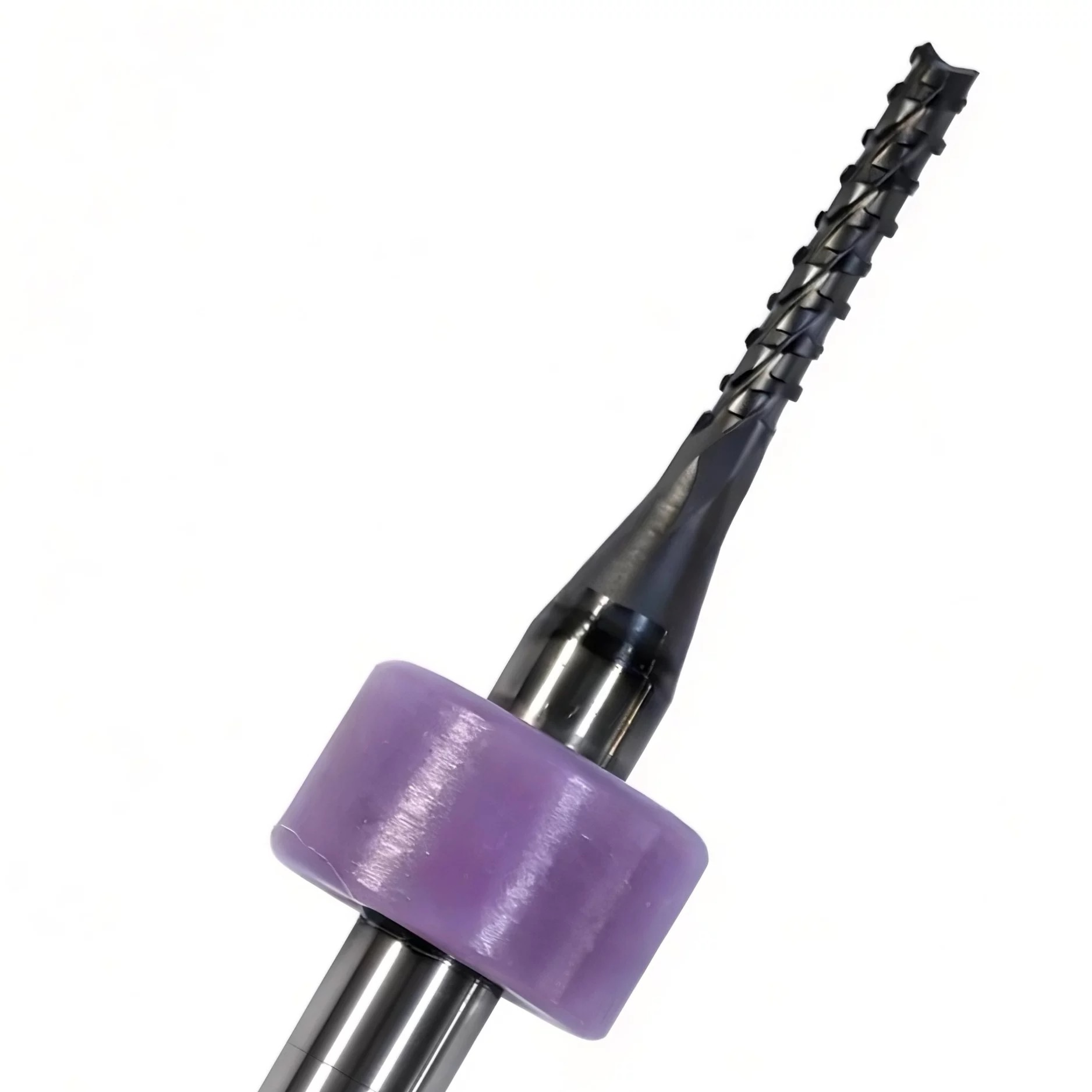
Las fresas de diamante para PCB, también conocidas como fresas de enrutamiento de PCB, fresas para placas de circuito impreso o fresas de grabado, se utilizan principalmente para el corte de contornos, ranurado, fresado con control de profundidad, ranurado en V, mecanizado de medios agujeros y biselado de contactos dorados en PCB; son las herramientas de carburo más utilizadas en los procesos de fabricación posteriores a la PCB.
Leer más
Dental-burs-1

Fresas dentales de diamante CVD

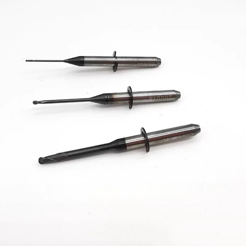
Corte de precisión a nivel micrométrico, que equilibra la máxima resistencia al desgaste con una experiencia clínica delicada. Esta serie de fresas dentales cuenta con un sustrato integrado de acero inoxidable/carburo de alta pureza, recubierto con nanodiamante CVD avanzado (o electrodeposición de partículas de diamante natural de alta densidad). Diseñadas para procedimientos clínicos de alta intensidad, como la preparación dental, el acceso a cavidades, la eliminación de caries, la restauración cosmética (preparación de carillas) y el corte de coronas/puentes. El recubrimiento de diamante ultraduro y uniformemente distribuido ofrece una eficiencia de corte agresiva a la vez que minimiza el calor por fricción para proteger la pulpa dental, convirtiéndola en la opción premium para la odontología digital moderna.
Leer más
Flat-bottom-cylindrical-end-mill-1

Fresa cilíndrica de fondo plano con recubrimiento de diamante

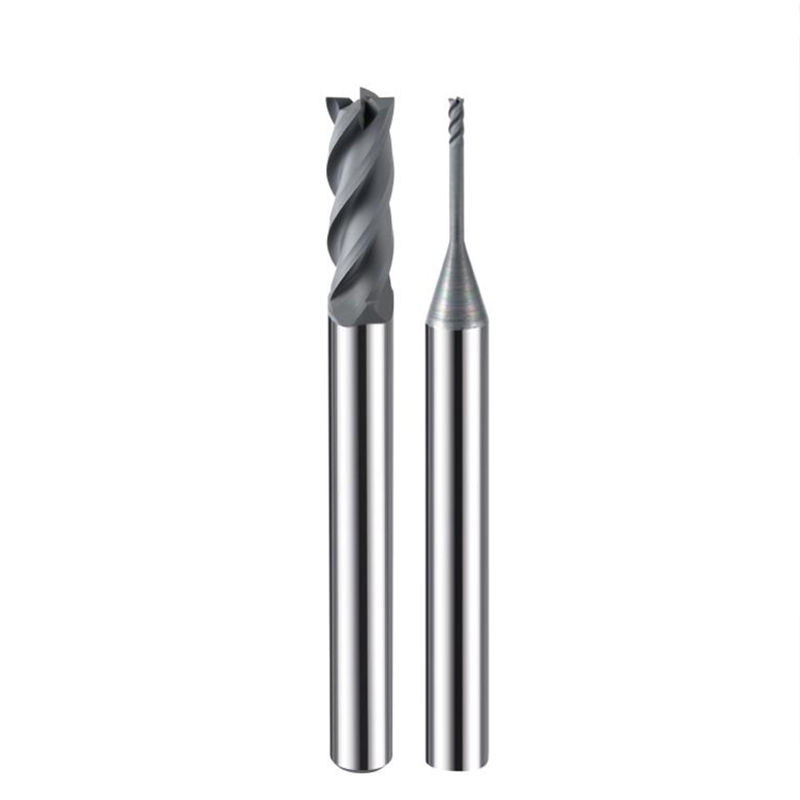
Diseño estándar de 2 o 4 filos con bordes de corte afilados y amplio espacio para la evacuación de virutas, adecuado para el desbaste y el semiacabado eficientes de electrodos de grafito.
Leer más
Get Standed
¿Sus herramientas están a la altura de la era de las piezas "difíciles de mecanizar"?

Dejar un mensaje

El grafito, la cerámica y la fibra de carbono son el futuro, pero son materiales que dañan las herramientas. Si aún utiliza recubrimientos tradicionales, está librando una batalla perdida.
Nuestro recubrimiento de diamante CVD (deposición química de vapor) crea una auténtica capa de diamante cristalino sobre el sustrato de carburo. No se trata solo de un acabado, sino de una protección.

¿Por qué los principales distribuidores eligen nuestra serie CVD?
1. Fricción ultrabaja: Evita la soldadura de virutas y la acumulación de calor.
2. Resistencia extrema a la abrasión: mantiene los filos de corte afilados 20 veces más tiempo.
3. Acabado superficial: Resultados similares a un espejo en la pieza de trabajo, sin necesidad de pulido secundario.


    Su nombre*

    Correo electrónico

    Teléfono

    WhatsApp*

    Mensaje

    Productos
    Contactos
    WhatsApp
    Correo electrónico